Showing posts with label diy. Show all posts

Saturday, February 23, 2013

Finally printing again

After several months of not printing I finally have a working 3D printer again - Yay! I can only blame myself for this; since I in my eagerness to improve the printer tore it apart before printing the new parts I needed. Even though my J-Head arrived swiftly I had nothing to mount it on...

J-Head Mk V-BV. Excellent build quality!
The aluminum plate mounted on top of the slide-bearings did not have enough stability using zip ties alone. I tried replacing the zip ties with brass wire (the sort used to hang paintings with), but that turned out even worse since you can't get the wire tight enough.

My best friend Sugru at work again.
Enter Sugru. I had a batch in the fridge that was nearing it's use-by date so why not try that. I made sure to protect the bearings with scotch tape so the sugru wouldn't stick - only support. Apply healthy amount of sugru and wait 24 hours. Worked like a charm!

Next I needed a new mechanism to feed the plastic. The easiest would have been to print something, but without a working printer that proved ... difficult.

Initial setup with the spring mechanism.
After a lot of thought and a fair number of iterations I came up with a design that let me have a spring as tension mechanism on the filament feeder.

Need more springs Scotty!
When calibrating the feed rate I quickly discovered that the original spring didn't have nearly enough force to keep the flow of plastic consistent - especially when the filament spool needed to be unreeled by the printer as well. Adding three more springs fixed that issue neatly - although it doesn't look as pretty any more.

First print: new tension lever.
First thing I printed was the Minimalistic Mk7 replacement by +Whosa whatsis. This is so I have a replacement part ready for if when my cobbled together setup fails.

As for now the feeder seems to hold up pretty good as well as consistent results. I think I'll keep it for a while. The J-Head I'm really impressed with; great build quality and excellent print result!

Tuesday, November 6, 2012

(Print)head in the right direction

While waiting for the print head from qu-bd to arrive I tried out fastening the Sumpod print head directly to the new aluminum y-axis.

Seen from below
The thickness of the plate, at 3mm, wasn't exactly ideal since the bottom part of the peek wouldn't quite go deep enough to make contact with the aluminum nozzle. That left a gap which potentially could leave room for the PFTE tube to expand like last time. I solved this by winding teflon tape around the PFTE tube - which then went into the nozzle.

I also wound teflon tape around the base of the peek in effect stabilizing the nozzle and minimizing the contact between the nozzle and aluminum plate - to reduce heat transfer. That way the peek hopefully would stay as cool as possible.

Top view
I just about managed to finish this setup before the new print head arrived this Saturday. Unfortunately I didn't get to test it since I never got the extruder part working correctly. Given time that too would surely have worked - but no use spending time on that now.

Nice packaging
Assembly of the MBE Extruder v9 was straight forward following the assembly pictures and videos on their web site. The only step that was unclear was if there were any extra steps necessary to install the resistor - since they only show the heat cartridge installation.

Assembly done
Now I need to figure out how to fasten the new print head to the y-axis. Could be a challenge since the base plate is a tiny bit too wide. I need to give it some thought.

On another note; we received our laser engraver/cutter at the office on Friday so now it should get a little bit easier to machine some parts.

40W CO2 laser from Full Spectrum

Sunday, September 16, 2012

Print Head Dissection

My "successful-print-happiness" didn't last long as by the next print the print head went back to it's old behavior. Particularly not feeding enough plastic and as a result screwing up the print by ripping up what's already there.

Not exactly 100% fill anymore...
Figuring something must have gone wrong with the print head/nozzle I did a bit of reading on the SUMPOD forum and although I couldn't find anyone having issues with my exact configuration of the print head I found a couple of possible culprits. Time to take it apart and see if I were right.

Right away I discovered that the aluminum nozzle was loose and not tightly fastened to the peek anymore. My guess it's caused by the repeated heating and cooling of the print head. I think it's the MakerBot manual that states you need to heat the print head before tightening the screw so that's something to keep in mind.

The PTFE tube (below) has expanded quite a bit.
As you can see from the picture above the PTFE tube is no longer straight and has a bump where the gap between the nozzle and peek had a gap. Because of the expanded tube I had to cut it off before I could completely disassemble the print head. The brown stuff at the bottom of the nozzle is plastic from the print process (before I got everything tuned it was quite messy).

The inside of the tube has expanded as well and makes a reservoir where the plastic can bunch up. This is probably the main reason the flow of plastic isn't as good as it should be.

Underside of the print head holder showing the MDF fitting around the PEEK.
I also believe the filament get's too hot further away from the nozzle - which will possibly make it expand while still in the PTFE tube. The previously measured temperature on the fastener seems to indicate this. One of the reasons might be that the MDF has been routed in such a way that the PEEK is incapsulated and therefore not able to cool down as efficiently.

There's also quite a lot of surface connection between the PEEK and the aluminum increasing the heat transfer even more. One way to lessen this would be to let the nozzle screw into the PEEK instead of the other way around. As I don't have access to a lathe I won't be able to test that theory, but someone else hopefully might.


I've had to cut my bowden tube twice now the remaining part is to short to work leaving my print head out of business. Since I'm expecting a replacement head from QU-BD soon I figure I might just as well start preparing my printer. The "old" setup don't have room for the new print head so I'll have to remove the MDF and fabricate a new y-axis. I'm thinking using more aluminum (same as in the print bed), but we'll see. I'll also move the y-motor off the carriage to reduce the weight as much as possible.

Friday, August 24, 2012

SUMPOD Heated Build Platform Part 2

I've been using the last week to put together "Heated Build Platform Mark II" consisting of aluminum sheet instead of glass. As I mentioned in my previous post I had an old Apple Pro cabinet where the side cover can be taken off easily. Being 3mm thick makes it perfect for this project.

Only negative thing was no access to a workshop or proper power tools...

I ended up using the non-metal wood hand saw.
Having read somewhere that it is possible to cut aluminum with blades meant for wood I though why not give it a try with my existing equipment.

Marked, taped and ready...
The saw was a cheapo so no big loss if it didn't work out - which it did :) I can't see any damage on the blade afterwards at least. Sawing aluminum this way is hard work so I won't recommend it if you have an alternative though.

New vs. old print bed.
Using the old platform as a template made it easier to drill holes in the right places etc. I made sure to tape the surface with masking tape first and to clamp the aluminum between two pieces of wood to avoid splinters. Sanded over all the edges with fine grit sanding paper afterwards.

Test fit.
Not shown here I made sure to test the heating functionality thoroughly before threading the wires and installing the platform.

Aluminum is a great heat-spreader, insuring pretty even temperature over the whole surface so that's great! Using a metal platform is not without it's drawbacks though. There's ample opportunity to electrocute yourself if you're not careful. Therefore I added two layers of Kapton to the underside before laying down the heat-wire. I might ground the plate at some point, but I'm not too worried since the platform will be warm when the power is on so I really don't want to touch it when it's active anyway.

The shielding on the wires I used are good up to 90C, which is more than enough for PLA, but If at some point I'm going to print ABS I probably have to rework that part.

Wired, levelled and ready for first print.
My second thermistor (RH16-4A104GB from MMC) worked out much better as well, being off by only one degree C. More than good enough for my purposes. I installed it roughly in the middle of the underside of the platform directly in contact with the aluminum and sealing the whole thing with Kapton.

Made sure there was enough wire to avoid it getting stuck or ripping anything loose.
Having made a few test prints there's no doubt the heated surface makes a huge difference in making the PLA stick to the surface. I haven't had one false start. That is, the plastic sticks on first try every time. I've had a couple of prints where very thin details becoming unstuck during the print, but for the most part it's been extremely good.

This time around I've been testing Slic3r which I like a lot for it's simplicity compared to Skeinforge - it's a lot faster as well being coded in C++. It seem to be a bit courser though. When it comes to fine detail and thin walls it sometimes leaves gaps, even when I have selected solid fill. That's something that I have to figure out.

The next issue to solve now is the feeder/printhead mechanism. I had the print head clog up three times the last couple of days and I'm still trying to figure out why. It seems to only happen on longer printruns and my initial guess is that there's a combination of several parts getting too hot. I've been playing around with increasing the filament extrusion-multiplier as well so there's a chance that's the reason. More testing needed :)

Just in case I ordered a new, and more compact, print head last night from QU-BD. Hopefully I will be able to use my existing Nema 17 stepper on this one. The bonus is that I eliminate the bowden tube and any slack in that type of setup. There is a disadvantage in moving more weight onto the y-axis so I'll have to test before saying anything for sure, but I might have to move the y-axis motor to the back of the printer frame and re-rig the belt.

So far I've been using the Sprinter firmware, but I think my next project will be to upgrade to Marlin since I've heard it's a bit better quality wise.

Wednesday, May 30, 2012

Alternative printer bed leveling

While I am waiting for the proper parts for leveling the print bed I came up with an alternative way. It's not something I would recommend if you have a heated print bed, but as I do not it's worth trying.

I found some packing foam and som IKEA cupboard bolts which should do the trick. The foam has the right springiness and by changing the size of the pieces you can get the proper resistance. Covering the whole back side of the bed was too much I found out.

Pink and stylish
Note the black drinking straws
Notice the four, black, drinking straws. These had the exact right diameter to match the predrilled holes and keeps everything nice and centered.

Before tightening of the bolts
First try. I found that since I had to tighten the rear bolts almost all the way the small pads of foam I started with weren't enough in the front.

After tightening of the rear side.
Added some more foam and the result turned out much better! Leveling took some time since tightening or loosening one screw affects the height of the nearby foam blocks so I had to re-measure and adjust the other bolts several times before it all was level. Still; I'm happy to be able to use the printer until I get some better parts.

Saturday, January 7, 2012

Finally done painting

Its been a busy month with work and all, but today I managed to actually paint the SUMPOD. Yay!

Two 500 ml cans later all parts got had two layers of glossy white paint - just about enough to cover the gray primer. I would have liked to have one more coat, but the store was closed at this point.

The smaller parts still drying.
For the two-sided parts I found stringing the parts up with fishing-line made it easy to paint both sides without waiting for the paint to dry.

I'm not entirely happy with the finished result as can be seen in the picture below. Overall the finish is good, but on some of the edges I probably should have primed and sanded a couple more times. MDF apparently needs more than three coats of primer even though they looked okay before I started applying white paint.

Still some rough spots on the edges.
Next time I have to paint MDF I'll probably go over all the edges with filler first thing to fill all the small gaps before the first coat of primer. Or maybe I'll just use regular paint which is much thicker and will saturate the fibers much faster.

As for now It will have to be good enough - it's only a 3D printer yes? I might go back and fix this later, but for now it'll do. Onwards to the rest of the build!

Sunday, December 4, 2011

Another Sumpod progress report

I've been a bit busy the last week so I've not been able to do much regarding the painting - other than adding a bit of filler for the holes in the sides of the MDF. Will buy more primer tomorrow.

I did however manage to start the soldering process. To get acquainted with my new soldering iron (FX-888 from Hakko) It was best to start with something simple - like soldering the "legs"/headers onto the Polulu stepper drivers.

Polulu driver.
After a couple of solder joints I could use the clamp. Please
excuse the lousy solder joints - still figuring this out.
These drivers are pretty small and light so it's a bit hard to get them soldered since you can't really hold them without attaching the headers first. Kind of a chicken and egg problem ;)

Using the Ramps board to hold the Polulu board.
A better way to do it is to use the Ramps board to hold the headers and then clamp that in the circuit board holder.

Sunday, November 27, 2011

Sumpod progress report

Not much progress to show, but on Wednesday I sanded down all the parts - which took about three hours by myself. Before painting on Saturday I also had to get off all the dust before I gave the parts another coat of primer. The larger surfaces are fine, but the ends sucks up primer like there's no tomorrow. So far I've used three 500ML boxes of primer and I'll probably need at least one more before I'm done.

According to the build descriptions at renaissance-engineer the feeder assembly should have more holes than this or am I missing something?

Front
Back/inside. I probably need to drill some holes for the
gear and motor fastings.
edit: I found the answer to my question on the SUMPOD forum: http://www.sumpod.com/forum/post/minor-problem-feeder-parts

Sunday, November 20, 2011

Sanding and more paint

Today my friend Tom dropped by and helped out with sanding and prepping of the parts that got their first coat yesterday. This is definitely the most boring part of the assembly so thanks a lot Tom!

The first box of primer was almost out so we were lucky the last box was just enough to give all the small parts their first coat and the box it's second. Tomorrow I'll need to go buy another box.
Seems like the MDF has different quality since several pieces
needed 3-4 passes (wet-wet) before I had good coverage. 
Like Fixer I assembled the box before painting to avoid
getting paint, and swelling, where it's not needed.
The MDF still bristles (is that a word?) a bit, but one more
round of sanding and primer and we should be good.
Inside the box as well as the large surfaces outside are
good enough at this point.
Earlier today I came over the Renaissance Engineer blog which, lucky for me, has a complete assembly guide for putting together the SUMPOD. He's not quite done with the wiring instructions yet, but they are coming. I'll probably use the rest of this week to get the painting done anyway so there's no rush.

Saturday, November 19, 2011

Cleanup and Paint

We've been quite busy with work the last week so I haven't been able to do anything more with the SUMPOD build until today. So this is my weekend project. Get all the MDF parts cleaned up and painted.

Parts all done
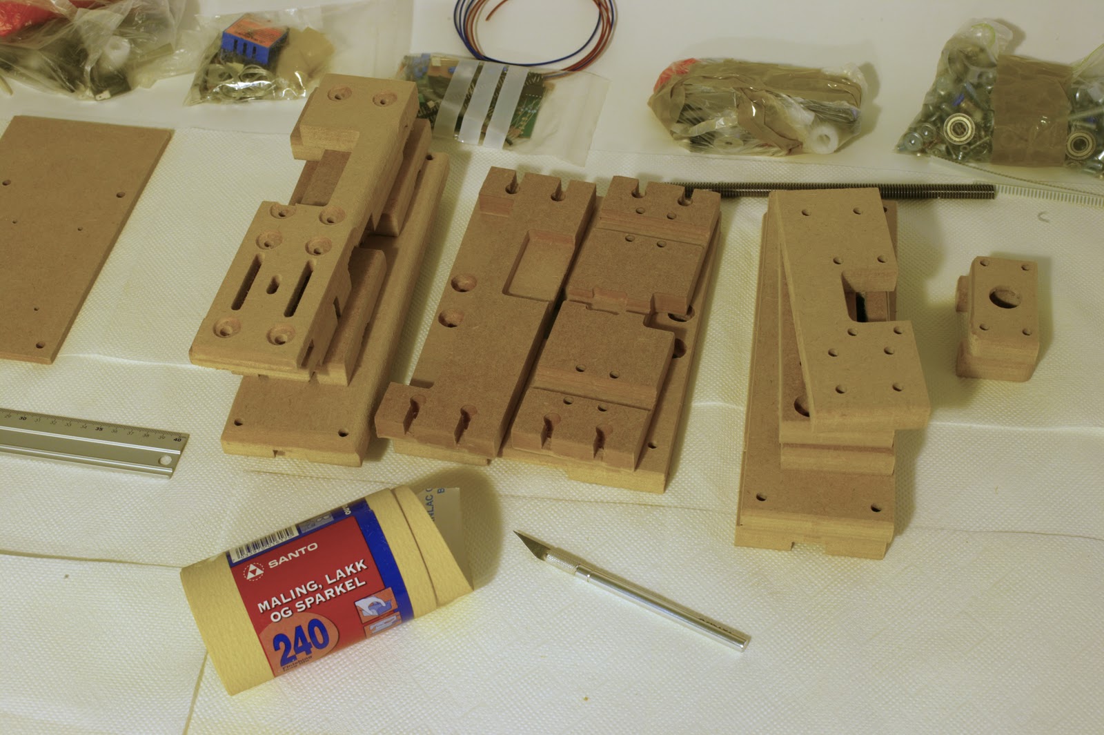
The prepping was quite easy as the parts looked fairly good from the start. All I had to do was go over all the edges with 240-grit sanding paper. I also used an X-Acto knife where the spindle had left small deposits of wood/paper. I imagine either the tool-bit was a bit dull, the routing-speed had been too high or the MDF too soft. Anyway, some cleanup should be expected in any project :)

Next I assembled the main box from the top and bottom plate as well as the 4 walls. Since I still don't have access to assembly instructions I had to guess which way the top and bottom plates should face. I'll have a look on the SUMPOD site and double-check their images when I get the time.

First coat of primer applied
The painting was pretty straight-forward and I got confirmation what I've read on other blogs - MDF needs a lot of paint. I ended up using almost a full spray-can (500 ML) of primer on the first coat. I seriously hope I don't have to use that much for the next two coats.

Tomorrow I'll try to get the rest of the parts primed and also apply a second coat to the main body.

Saturday, November 12, 2011

SUMPOD unboxing

DIY 3D printing is all the rage these days and a while ago I ordered one of my own. Yesterday I finally received the SUMPOD so today it was time for unboxing! At first I thought the box was very small, but when I opened it up I was surprised by how much there was inside.

Not more than 36cm on the longest edge.

Box filled to the brim - a small sample of PLA wire on top (red).

First step was to lay out all the parts and try to get some feel of what I have gotten myself into - after all I'm supposed to assemble this myself. That includes painting and finishing all the MDF parts as well as soldering the controller electronics and finding suitable software. All without a manual ;)

All the parts. Great packing skills!
 Before I can start painting I need to do some basic cleanup though.

The overall finish is good, but some cleanup is needed.
Looking very much forward to starting the actual build :)

Sunday, November 6, 2011

DIY Roasted Müesli


Time for a non-techy post ;) This time home made müesli.

Recipe
3-4 DL Oat flakes
1 DL Almonds
1 DL Hazelnuts
1 DL Walnuts
1 DL Sunflower seeds
1 DL Pumpkin seeds
1 DL Dried coconut mass
1 DL Flaxseed
1-2 DL Soy flakes

1 Tsp Salt
2 Tbsp Cinnamon
A pinch of vanilla powder

1 Tbsp Lemon-/lime juice
5 Tbsp Canola oil
5 DL Water

Preparation
Use a sharp knife and chop all the nuts and mix them with the rest of the dry ingredients (except the soy flakes) in a big bowl. Mix the water, oil and lemon-/lime juice in a separate container and stir it in a little bit at the time until it's all evenly distributed.

Prepare two deep pans with baking paper and spread the mixture evenly. Put both pans into the oven at 160-170°C for 15 minutes and then switch around the pans and roast for another 15 minutes. Add the soy flakes, stir around a bit and let it roast for another 5-10 minutes with the hot air fan engaged (if you have one). Be careful that you don't burn the mixture or dry it out to much!

Let cool in pan before storing in a air-tight container. You might also add raisins at this step if you like.

Serving
Enjoy with Türkish yoghurt and acacia honey - or if you you would like to stay away from dairy products; soya milk works very well as well.

Sunday, April 26, 2009

DIY Electronics

So I've always been interested in electronics and all kinds of gizmos, but lately I've been playing with the idea of trying to come up with some cool stuff myself. Not quite sure what I'm going to make yet, but that'll come later.

There's a lot of great resources and inspiration out there, like Instructables, Hack a Day and Make Magazine. I know I would like to have a closer look at the Arduino and make something out of that, but since I haven't tinkered with electronics for years I found it best to start simple and refresh the basics. Sparkfun has a great tutorials section where they go through a bunch of stuff ranking simple to advanced.

There are basically two standard ways of making your own PCBs. The first is to use a laser printer to print out your circuitry and then transfer the toner to the PCB, clean it, etch it (using the toner as a mask) and then remove the toner with acetone. The second also uses a laser printer, but printing on a transparecy instead, using that as a mask while exposing the PCB to UV light before etching it. The main issue with both these methods is that you have to own a laser printer and one that uses enough toner to make the traces black enough that either etching fluid or UV light destroys the fine detail.

That got me thinking. Why isn't there an easier way of creating your own boards with as few steps as possible? Wouldn't it be nice to be able to draw up the ciruit using some form of laser?

Googling a bit I came over the macetech.com blog that proposed to use a laser to remove black paint from a PCB. The paint would take the place of the toner so you can skip that step entirely. Make has a similar article doing the same thing. As both of these posts mention, this method is not perfect. First of all using spray paint doesn't guarantee an even distribution of paint and the laser doesn't remove all of the paint as well - leaving you to wash of the rest. That again might destroy the any fine traces in the design. However; they both also mention that this method creates superb detail!

Taking it a step further a Polish research group came up with a way of doing Laser Direct Imaging (LDI) using UV laser a telescope and an optical scanner. Since they use a UV laser they rely on UV sensitive PCB's removing one more step; the toner/paint. The process is described in detail here and it was mainly created to be able to do ultra-fine traces for the circuitry of the future. In that aspect they succeded and while it's great a sollution it's not entirely feasible for us mere mortals.

Francois Dubrulle at HoloLab has made a UV photoplotter that does exactly what I want. Although his web-page lacks on details it shows it's possible. The main issue with this design, as he mention, is the low power of the laser (1mW) which limits the the speed of the print and it takes as much as two hours to finish one board. Doing prototyping and not volume production I don't mind waiting a bit to have PCB's produced this way since I can do something else in the meanwhile.

There are a lot of resources on making your own CNC mill and a 1mW UV diode has become pretty cheap so making one of these for myself should be feasible. Taking it one step further one could use the same CNC, switch out the UV lightsource with a laser and use that to make the screens for the solder and the laquer.

Maybe this will be my next project?