Sunday, April 28, 2013

Oculus Rift: First Impressions

This Monday UPS delivered my Oculus Rift - which were a pleasant surprise since it's still, as of today, which is Sunday, listed as "Processing for delivery" on my account page on the Oculus web site.

Shipping box.
Nice and sturdy packaging.
High product value going on here. Even if it's "just" a developers kit. Me like :)
As I'll probably will be bringing the Rift with me the case will be handy to have.
As the OS X devkit weren't available when I got the kit didn't have anything to test it on as I'm mostly on Mac and Linux these days. Still - the new PC arrived after a couple of days so no big deal. Had to fiddle a bit around to get it up and running though; It's been quite a while since I put together a "gaming rig" and a dated BIOS prevented me from booting with the Nvidia card.

Getting the system up and running with Windows 7 and the rest of the software needed took most of yesterday so it weren't until today I could hook up the Rift and do a test run. Very excited!

Current setup with a small 1280x720 display to extend/mirror the Rift. Oh, and a big iMac 27" in the background. Kind of the reason I don't want any more big displays at the moment ;)
My first impression, when I put on the goggles, were: "Wow! Those pixels are big!". Which is nothing new, and something I were prepared to experience, but still. On the other hand I did fire up the goggles while still on the desktop and a pure, blue, background doesn't give you much to look at. Having since learned that you can start the Unity Tuscany demo on your other display and switch it over to the Rift using the F9 key makes things a bit easier. As others have noted; you can't navigate your desktop with the Rift!

It's a must to have a second monitor to navigate the desktop and in-game menus.
I know there's work being done in this area, but I haven't had time to test it out myself yet. There's an active thread on the MTBS3D forum about this.

That said; the Tuscany demo is very nice and you kind of forget those pixels when you move around - which is the best part. The Rift tracks your head movement very precisely and you really get the feeling you're "there". Until, after a couple of minutes, you get pretty nauseous. At least I did...

As I'm prone to motion sickness this didn't surprise me at all, but I think the main reason in this case were from moving around using the keyboard and mouse. As long as I'm in one place, just looking around I didn't feel a thing. My hope is that having positional tracking as well will alleviate this since the cues picked up by the middle ear will correlate to what the eyes see. I might try to implement some means to test this later on. Later when I tried out some other demos the effect weren't nearly as strong so I hope it will pass entirely in the future.

Firing up Hawken were a nice surprise. As it's not released with Rift support yet, at first I didn't understand why my POW was looking straight down, until I saw the headset laying on the desk next to me with the front down. Seems like the tracking works as expected, but the camera-rendering isn't enabled yet. There might be a way of enabling this in an ini file, but I haven't gotten that far yet. The same goes for the Citadel demo in the Unreal Developers Kit. Works fine with the head tracking, but I need to tweak the same (?) ini file to turn on the 3D view. Something to try out tomorrow.

The Rift being a developers kit I didn't expect too much, but so far I'm very happy with it. If the guys at Oculus VR manage to implement positional tracking as well as a more pixel-dense display I think the consumer version will be great product. And I hope this time around VR won't flop like it did back in the 90s.

Sunday, March 17, 2013

Merging multiple DVI signals using an FPGA

A small followup to my previous post. Inspired by an article on Hackaday I did some more research on the use of FPGA to manipulate DVI streams.

It seems this has already been done. I came over this project at the Institute of Visual Computing in Germany. Direct link to pdf here. They talk about several different methods to parallelize rendering of a scene. "Sort-first" is a way of splitting the image into multiple parts (quadrants) and have different computers render each one - then combining it with a custom FPGA.

The downside is that their solution seem to require genlocked cards. This would require professional GPU's like the Quadro line from NVidia which are not exactly the best for gaming and also carries a high cost. On the other hand, there is enough RAM on the FPGA that they can handle +- 2 lines difference in sync using a small buffer/FIFO. The main difference to what we need is that we have both GPUs mounted in the same PC. That way, when we tell the 3D engine to start sending the two frames rendered in each GPU they will start at the same time - more or less. Hopefully this will let us get away without using genlock, but that's still just a theory. Running high-rez at 60Hz the timing will be tight anyway.

Update:
It seems the 618 series DVI comparator from Colorado Video has the capability to do what we require. Unfortunately they do not mention what the max resolution is, if you need genlocked signals or what kind of latancy (if any) the unit has. At $1390 it's not exactly cheap either. Good to know someone has done it though.

Thursday, March 7, 2013

Maximizing Performance for VR

Like everybody else that took part in the Kickstarter I'm eagerly waiting for my Oculus Rift. Latest news is that they will start shipping kits later this month so hopefully the wait will be over soon!

While we wait there's a lot of time for speculation. For example; how will it perform with modern games? Doom 3 BFG is after all not the most taxing game any more. Most modern graphic engines require a pretty beefy hardware setup - both on the CPU and GPU side. Even then you aren't guaranteed a minimum of 60 fps all the time. When wearing a HMD like the Rift anything below 60 fps could ruin the immersive experience as a result of stuttering.

As the screen of the Rift developer kit only has a resolution of 1280x800 pixels it's not bad as for pixel fill, but it can still tax the computer when rendering two eyes/cameras. Nobody yet know how pixel-heavy the consumer version will be, but 1920x1080 is not totally unlikely.

So how do we ensure a high and consistent frame rate? First of all; turning off vsync would be a bad idea since tearing will destroy the immersion just as much as lower frame rates. Turning off high detail, anti-aliasing, shadows etc would for sure make the games run smoother, but where's the fun in that? Also; as the Rift has relatively low horizontal resolution per eye (1280 / 2 = 640 pixels) you'll probably need some anti aliasing to take care of hard edges. This is something that has already been confirmed by people that has tried out early versions of the Rift.

Obviously adding one or more graphic cards would help, but it's not that easy. SLI or CrossFire are not good solutions when generating VR related imagery since they both add 1+ frame of latency depending on the mode used. That's 16ms at 60Hz which automatically puts us above 20ms latency since rendering one frame takes 1 frame already. They can also in some cases suffer from other artefacts.

Latency, in combination with frame rate, is a big factor since you'll easily develop motion sickness if the computer generated world you perceive through your eyes does not match up with the actual movement your head performs and your middle ear detects. Both Michael Abrash of Valve Software and John Carmack at ID Software have written at length about latency and suggests ways to at least partly mitigate it. Both articles are well worth a read. The main goal would be to get latency below 20ms as anything below that would not be noticeable for most of us.

What we need is a way to render the left and right eye on separate graphic cards. Having the game engine support this, in comparison to rendering both views through one card shouldn't be too hard. Back in the "old days" we would do this when working with stereoscopic content - since we had to use two projectors with polarized glass to show the content so it's not that different. The difficult part is to merge them back together into one signal - as that is what the Rift expects.

A custom FPGA could be the solution. I'm no expert, but since we won't manipulate the signal in any way - the computational requirements shoudn't be too bad - especially for the resolutions we are talking about for the developers kit.

Since DVI, as I understand it, don't send the whole frame as a packet, but streams each pixel as if it were an analog video signal, we should be able to mix, or rather switch, the signals using the FPGA in real time. This is important since we don't want to introduce any more latency to the pipe. Since the left and right image will be located at each halve of the frame respectively we would simply tell the FPGA to switch between the two signals when passing the middle of the screen and back again at the right edge of the screen.

There are, however, a couple of challenges with this solution, the most prominent being sync (or genlock/framelock in TV-lingo). We would need to ensure that each pixel on the screen, be it for the left or right eye, scans out at the precise same time or else we would get artifacts in the form of slipping scan lines and skewing of the image.


Taking it one step further; to reduce the latency on the computer/GPU side if things one might even be able to have the computer render frames at 120Hz, but only let half of them through the FPGA - giving the display 60Hz - which it can handle. Although that would probably require some kind of buffering since the clock signal of the input would be half of what the display requires.

I'm making quite a few assumptions here, but it would be very interesting to test this out properly. I wonder if theres's time to learn VHDL before my Rift arrives?

Saturday, February 23, 2013

Finally printing again

After several months of not printing I finally have a working 3D printer again - Yay! I can only blame myself for this; since I in my eagerness to improve the printer tore it apart before printing the new parts I needed. Even though my J-Head arrived swiftly I had nothing to mount it on...

J-Head Mk V-BV. Excellent build quality!
The aluminum plate mounted on top of the slide-bearings did not have enough stability using zip ties alone. I tried replacing the zip ties with brass wire (the sort used to hang paintings with), but that turned out even worse since you can't get the wire tight enough.

My best friend Sugru at work again.
Enter Sugru. I had a batch in the fridge that was nearing it's use-by date so why not try that. I made sure to protect the bearings with scotch tape so the sugru wouldn't stick - only support. Apply healthy amount of sugru and wait 24 hours. Worked like a charm!

Next I needed a new mechanism to feed the plastic. The easiest would have been to print something, but without a working printer that proved ... difficult.

Initial setup with the spring mechanism.
After a lot of thought and a fair number of iterations I came up with a design that let me have a spring as tension mechanism on the filament feeder.

Need more springs Scotty!
When calibrating the feed rate I quickly discovered that the original spring didn't have nearly enough force to keep the flow of plastic consistent - especially when the filament spool needed to be unreeled by the printer as well. Adding three more springs fixed that issue neatly - although it doesn't look as pretty any more.

First print: new tension lever.
First thing I printed was the Minimalistic Mk7 replacement by +Whosa whatsis. This is so I have a replacement part ready for if when my cobbled together setup fails.

As for now the feeder seems to hold up pretty good as well as consistent results. I think I'll keep it for a while. The J-Head I'm really impressed with; great build quality and excellent print result!

Tuesday, December 4, 2012

Print head progress report

Just a quick update regarding the print head from QU-BD. First impression was really good: the assembled hot- and cold end looked professional with a thought through design. I was very eager to try it out, but started off simple, just hand-feeding the filament without engaging the motor.

At 180C the plastic flowed perfectly for about 10 cm (raw filament) - then abruptly stopped! Even using pliers I could not force any more filament through the nozzle. Pulling out the filament I noticed a small plug at the end. Cutting this off and re-threading the filament let me extrude again, but as soon as I made a stop, or after about 10 cm, it would stop again. Feeding and then retracting before feeding again helped some of the time, but no matter of increasing/decreasing the temperature made any difference.

After a lot of fiddling and reading the various threads at Fabric8r I concluded that there was no use even trying the motor before I disassembled the print head. Which was easier said than done considering the plastic had leaked and clogged up the inside of the heater block. Instead of warming it up I soaked it in isopropanol over night - which kind of worked.

Leaked plastic.
More plastic at the bottom and inside.
It's hard to see in the pictures, but you can see the plastic around the brass nozzle and at the top of the heating block. This being caused by the brass nozzle and steel rod not being pressed together tight enough. The leakage apparently causes drag inside the nozzle and makes the plastic hard to press out through the nozzle. When stopping the PLA will expand in the heat and cause total blockage.

Fixing this should be easy enough, cleaning the parts, re-tighten and reassemble the whole thing. Although I'm not going to do that. I'm sure one can get nice prints with this head, but after reading about all the other issues people on the Fabric8r forum are having with not just the hot-head, but the feeder as well I can't be bothered. All very fixable I'm sure, but requiring a lot of fiddling and even then the prints tend to not be that stable between sessions.

So being kind of fed up not being able to print I decided to order a new print head. This time a more proven design: the J-Head Mk V-BV recommended on the RepRap wiki. The one I ordered has a .4mm nozzle and is made for 1.75mm filament. A .4 mm nozzle (the same as I've been using from the beginning) should be easier on the motor as well although I won't be getting as fine details as with a .35mm nozzle (like in the QU-BD head). The bigger nozzle should be more forgiving in regards to filament as well and not clog up as easily.

I got an e-mail yesterday that it has been shipped so back to playing the waiting game...

Saturday, December 1, 2012

Lazurs and Cookies

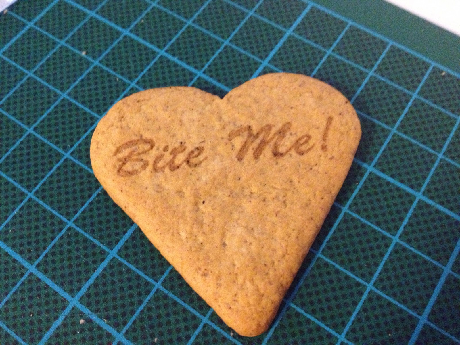
We bought a box of gingerbread cookies at work yesterday which made for an excellent test of the 40W CO2 lasers engraving capability.

Based on previous tests with engraving on cardboard we started out with relatively low settings. Press "go" and soon the lovely smell of gingerbread cookies hit us. And yes; the air exhaust was on.

First try. Engraving @ 60% power, 100% speed and 250dpi.
For the next try I lowered the power, but increased the dpi - which ended up giving the engraving more contrast (and smell).

Second try. Engraving @ 50% power, 100% speed and 500dpi.
Both engravings came out pretty nice and sharp even though the focus was about a millimeter off. Next off was cutting. This time I made sure the focus was correct.

You can do cutting as well. 25% speed and 100% power.
It did cut pretty well - although the smell of burned cookies was pretty strong for a good while after the cut was done. It would be fun to bake sheets of gingerbread and then cut them in the laser cutter to make a gingerbread house, but one would have to let the finished pieces air for a while outside before assembly.

As for all of these - I definitely wouldn't eat any of them...


Update:
Looks like Johan von Konov has taken this all the way in Laser Cut Miniature Gingerbread House.

Tuesday, November 6, 2012

(Print)head in the right direction

While waiting for the print head from qu-bd to arrive I tried out fastening the Sumpod print head directly to the new aluminum y-axis.

Seen from below
The thickness of the plate, at 3mm, wasn't exactly ideal since the bottom part of the peek wouldn't quite go deep enough to make contact with the aluminum nozzle. That left a gap which potentially could leave room for the PFTE tube to expand like last time. I solved this by winding teflon tape around the PFTE tube - which then went into the nozzle.

I also wound teflon tape around the base of the peek in effect stabilizing the nozzle and minimizing the contact between the nozzle and aluminum plate - to reduce heat transfer. That way the peek hopefully would stay as cool as possible.

Top view
I just about managed to finish this setup before the new print head arrived this Saturday. Unfortunately I didn't get to test it since I never got the extruder part working correctly. Given time that too would surely have worked - but no use spending time on that now.

Nice packaging
Assembly of the MBE Extruder v9 was straight forward following the assembly pictures and videos on their web site. The only step that was unclear was if there were any extra steps necessary to install the resistor - since they only show the heat cartridge installation.

Assembly done
Now I need to figure out how to fasten the new print head to the y-axis. Could be a challenge since the base plate is a tiny bit too wide. I need to give it some thought.

On another note; we received our laser engraver/cutter at the office on Friday so now it should get a little bit easier to machine some parts.

40W CO2 laser from Full Spectrum