Tuesday, December 4, 2012

Print head progress report

Just a quick update regarding the print head from QU-BD. First impression was really good: the assembled hot- and cold end looked professional with a thought through design. I was very eager to try it out, but started off simple, just hand-feeding the filament without engaging the motor.

At 180C the plastic flowed perfectly for about 10 cm (raw filament) - then abruptly stopped! Even using pliers I could not force any more filament through the nozzle. Pulling out the filament I noticed a small plug at the end. Cutting this off and re-threading the filament let me extrude again, but as soon as I made a stop, or after about 10 cm, it would stop again. Feeding and then retracting before feeding again helped some of the time, but no matter of increasing/decreasing the temperature made any difference.

After a lot of fiddling and reading the various threads at Fabric8r I concluded that there was no use even trying the motor before I disassembled the print head. Which was easier said than done considering the plastic had leaked and clogged up the inside of the heater block. Instead of warming it up I soaked it in isopropanol over night - which kind of worked.

Leaked plastic.
More plastic at the bottom and inside.
It's hard to see in the pictures, but you can see the plastic around the brass nozzle and at the top of the heating block. This being caused by the brass nozzle and steel rod not being pressed together tight enough. The leakage apparently causes drag inside the nozzle and makes the plastic hard to press out through the nozzle. When stopping the PLA will expand in the heat and cause total blockage.

Fixing this should be easy enough, cleaning the parts, re-tighten and reassemble the whole thing. Although I'm not going to do that. I'm sure one can get nice prints with this head, but after reading about all the other issues people on the Fabric8r forum are having with not just the hot-head, but the feeder as well I can't be bothered. All very fixable I'm sure, but requiring a lot of fiddling and even then the prints tend to not be that stable between sessions.

So being kind of fed up not being able to print I decided to order a new print head. This time a more proven design: the J-Head Mk V-BV recommended on the RepRap wiki. The one I ordered has a .4mm nozzle and is made for 1.75mm filament. A .4 mm nozzle (the same as I've been using from the beginning) should be easier on the motor as well although I won't be getting as fine details as with a .35mm nozzle (like in the QU-BD head). The bigger nozzle should be more forgiving in regards to filament as well and not clog up as easily.

I got an e-mail yesterday that it has been shipped so back to playing the waiting game...

Saturday, December 1, 2012

Lazurs and Cookies

We bought a box of gingerbread cookies at work yesterday which made for an excellent test of the 40W CO2 lasers engraving capability.

Based on previous tests with engraving on cardboard we started out with relatively low settings. Press "go" and soon the lovely smell of gingerbread cookies hit us. And yes; the air exhaust was on.

First try. Engraving @ 60% power, 100% speed and 250dpi.
For the next try I lowered the power, but increased the dpi - which ended up giving the engraving more contrast (and smell).

Second try. Engraving @ 50% power, 100% speed and 500dpi.
Both engravings came out pretty nice and sharp even though the focus was about a millimeter off. Next off was cutting. This time I made sure the focus was correct.

You can do cutting as well. 25% speed and 100% power.
It did cut pretty well - although the smell of burned cookies was pretty strong for a good while after the cut was done. It would be fun to bake sheets of gingerbread and then cut them in the laser cutter to make a gingerbread house, but one would have to let the finished pieces air for a while outside before assembly.

As for all of these - I definitely wouldn't eat any of them...


Update:
Looks like Johan von Konov has taken this all the way in Laser Cut Miniature Gingerbread House.

Tuesday, November 6, 2012

(Print)head in the right direction

While waiting for the print head from qu-bd to arrive I tried out fastening the Sumpod print head directly to the new aluminum y-axis.

Seen from below
The thickness of the plate, at 3mm, wasn't exactly ideal since the bottom part of the peek wouldn't quite go deep enough to make contact with the aluminum nozzle. That left a gap which potentially could leave room for the PFTE tube to expand like last time. I solved this by winding teflon tape around the PFTE tube - which then went into the nozzle.

I also wound teflon tape around the base of the peek in effect stabilizing the nozzle and minimizing the contact between the nozzle and aluminum plate - to reduce heat transfer. That way the peek hopefully would stay as cool as possible.

Top view
I just about managed to finish this setup before the new print head arrived this Saturday. Unfortunately I didn't get to test it since I never got the extruder part working correctly. Given time that too would surely have worked - but no use spending time on that now.

Nice packaging
Assembly of the MBE Extruder v9 was straight forward following the assembly pictures and videos on their web site. The only step that was unclear was if there were any extra steps necessary to install the resistor - since they only show the heat cartridge installation.

Assembly done
Now I need to figure out how to fasten the new print head to the y-axis. Could be a challenge since the base plate is a tiny bit too wide. I need to give it some thought.

On another note; we received our laser engraver/cutter at the office on Friday so now it should get a little bit easier to machine some parts.

40W CO2 laser from Full Spectrum

Sunday, September 16, 2012

Print Head Dissection

My "successful-print-happiness" didn't last long as by the next print the print head went back to it's old behavior. Particularly not feeding enough plastic and as a result screwing up the print by ripping up what's already there.

Not exactly 100% fill anymore...
Figuring something must have gone wrong with the print head/nozzle I did a bit of reading on the SUMPOD forum and although I couldn't find anyone having issues with my exact configuration of the print head I found a couple of possible culprits. Time to take it apart and see if I were right.

Right away I discovered that the aluminum nozzle was loose and not tightly fastened to the peek anymore. My guess it's caused by the repeated heating and cooling of the print head. I think it's the MakerBot manual that states you need to heat the print head before tightening the screw so that's something to keep in mind.

The PTFE tube (below) has expanded quite a bit.
As you can see from the picture above the PTFE tube is no longer straight and has a bump where the gap between the nozzle and peek had a gap. Because of the expanded tube I had to cut it off before I could completely disassemble the print head. The brown stuff at the bottom of the nozzle is plastic from the print process (before I got everything tuned it was quite messy).

The inside of the tube has expanded as well and makes a reservoir where the plastic can bunch up. This is probably the main reason the flow of plastic isn't as good as it should be.

Underside of the print head holder showing the MDF fitting around the PEEK.
I also believe the filament get's too hot further away from the nozzle - which will possibly make it expand while still in the PTFE tube. The previously measured temperature on the fastener seems to indicate this. One of the reasons might be that the MDF has been routed in such a way that the PEEK is incapsulated and therefore not able to cool down as efficiently.

There's also quite a lot of surface connection between the PEEK and the aluminum increasing the heat transfer even more. One way to lessen this would be to let the nozzle screw into the PEEK instead of the other way around. As I don't have access to a lathe I won't be able to test that theory, but someone else hopefully might.


I've had to cut my bowden tube twice now the remaining part is to short to work leaving my print head out of business. Since I'm expecting a replacement head from QU-BD soon I figure I might just as well start preparing my printer. The "old" setup don't have room for the new print head so I'll have to remove the MDF and fabricate a new y-axis. I'm thinking using more aluminum (same as in the print bed), but we'll see. I'll also move the y-motor off the carriage to reduce the weight as much as possible.

Sunday, August 26, 2012

Successful Print

A small followup to Fridays post. I've been doing more printing and the print head clogs up roughly at the same time every time with the result of a ruined print and needing to yank out the PLA. The increased value of the extrusion-multiplier had nothing (or very little at least) to do with it either. After a failed attempt I measuring the temperature on the push fitting to 60 degrees C! Too hot to touch.

Aluminum foil heat sinks.
I had a couple of small heat sinks, but no thermal compound and way of fastening them so I brought out a sheet of aluminum foil which I folded, cut and attached to the print head.


I also added a fan blowing air over the improvised cooling solution. Not pretty, but as a proof of concept more than good enough. Press "Print" and wait...

Roghly three hours later I had my result:

A little bit of cleanup needed, but apart from that very nice.
Pretty much perfect! The print head oozes a bit so there's small bits/balls of plastic here and there that needs to be cleaned up, but over all I'm very pleased with the result.

Friday, August 24, 2012

SUMPOD Heated Build Platform Part 2

I've been using the last week to put together "Heated Build Platform Mark II" consisting of aluminum sheet instead of glass. As I mentioned in my previous post I had an old Apple Pro cabinet where the side cover can be taken off easily. Being 3mm thick makes it perfect for this project.

Only negative thing was no access to a workshop or proper power tools...

I ended up using the non-metal wood hand saw.
Having read somewhere that it is possible to cut aluminum with blades meant for wood I though why not give it a try with my existing equipment.

Marked, taped and ready...
The saw was a cheapo so no big loss if it didn't work out - which it did :) I can't see any damage on the blade afterwards at least. Sawing aluminum this way is hard work so I won't recommend it if you have an alternative though.

New vs. old print bed.
Using the old platform as a template made it easier to drill holes in the right places etc. I made sure to tape the surface with masking tape first and to clamp the aluminum between two pieces of wood to avoid splinters. Sanded over all the edges with fine grit sanding paper afterwards.

Test fit.
Not shown here I made sure to test the heating functionality thoroughly before threading the wires and installing the platform.

Aluminum is a great heat-spreader, insuring pretty even temperature over the whole surface so that's great! Using a metal platform is not without it's drawbacks though. There's ample opportunity to electrocute yourself if you're not careful. Therefore I added two layers of Kapton to the underside before laying down the heat-wire. I might ground the plate at some point, but I'm not too worried since the platform will be warm when the power is on so I really don't want to touch it when it's active anyway.

The shielding on the wires I used are good up to 90C, which is more than enough for PLA, but If at some point I'm going to print ABS I probably have to rework that part.

Wired, levelled and ready for first print.
My second thermistor (RH16-4A104GB from MMC) worked out much better as well, being off by only one degree C. More than good enough for my purposes. I installed it roughly in the middle of the underside of the platform directly in contact with the aluminum and sealing the whole thing with Kapton.

Made sure there was enough wire to avoid it getting stuck or ripping anything loose.
Having made a few test prints there's no doubt the heated surface makes a huge difference in making the PLA stick to the surface. I haven't had one false start. That is, the plastic sticks on first try every time. I've had a couple of prints where very thin details becoming unstuck during the print, but for the most part it's been extremely good.

This time around I've been testing Slic3r which I like a lot for it's simplicity compared to Skeinforge - it's a lot faster as well being coded in C++. It seem to be a bit courser though. When it comes to fine detail and thin walls it sometimes leaves gaps, even when I have selected solid fill. That's something that I have to figure out.

The next issue to solve now is the feeder/printhead mechanism. I had the print head clog up three times the last couple of days and I'm still trying to figure out why. It seems to only happen on longer printruns and my initial guess is that there's a combination of several parts getting too hot. I've been playing around with increasing the filament extrusion-multiplier as well so there's a chance that's the reason. More testing needed :)

Just in case I ordered a new, and more compact, print head last night from QU-BD. Hopefully I will be able to use my existing Nema 17 stepper on this one. The bonus is that I eliminate the bowden tube and any slack in that type of setup. There is a disadvantage in moving more weight onto the y-axis so I'll have to test before saying anything for sure, but I might have to move the y-axis motor to the back of the printer frame and re-rig the belt.

So far I've been using the Sprinter firmware, but I think my next project will be to upgrade to Marlin since I've heard it's a bit better quality wise.

Sunday, August 12, 2012

SUMPOD Heated Build Platform Retrofit

There's not been much progress on my 3D printer during the summer months since I haven't been much home, but this last week I've had a bit of progress.

Where I left off before summer showed I had some challenges to overcome with the build quality.

Failed prints
Mostly I've been playing around with the settings in Skeinforge - which is a hugely complex software for slicing up the 3D model and preparing the g-code for the printer. Using Airtrippers PLA settings as a starting point I got pretty good quality for the bottom and side walls, but the filling still gives me issues. As seen in the picture the print head tears up the fine inner walls in the model and produces big, gaping holes that the printer can't close when doing the top layer at the end.

I suspect this mainly is caused by to low flow of material on the interior walls, but I haven't been able to find the right setting to increase this yet. More testing needed. I might go back to scratch and test with coarser settings, i.e. thicker layers, to see if that helps as well since part of the problem is that the previous layer stick to the printer head.

Another, frustrating, issue is that the printer seems to print when moving from one position at one side of the model, to another at the other side. This leaves a slightly higher stripe of plastic that creates non uniform surface on the next layer. This can be seen particularly good at the center object on the bottom layer on the picture above. I don't think it has to do with residue plastic continuing to ooze from the print head since it seems to consistent for that - but I could always be wrong.

Getting the the print to stick to the build platform has also been challenging. At first I used the provided MDF platform with blue masking tape. Depending on the temperature in the room I had to restart the build 5-10 times before the PLA would stick properly. Increasing the temperature of the print head above 185 degrees C does not help with the brand of PLA I'm using at the moment. I've also played around with increasing/decreasing the distance between the print head and the build platform up until the point of the filament jamming.

Changing the build platform to use glass seem to help a bit - when heating the glass with a hair dryer directly before starting a print. Still takes quite a few tries to have it stick. Seems like the printer doesn't feed enough material at the beginning as well. I'm printing without a raft since I can't be bothered to remove it afterwards ;)

Glass picture frame from Clas Ohlson. Cheap at just over €1.
Still covering the glass with blue painters tape
Seeing heat was the way to go - a heated build platform was the next logical step. I ordered a huge (20 cm wide) roll of Kapton tape from e-bay to avoid having to overlap when covering the platform. Thinking Nicrome wire easy to source I didn't order any, but I couldn't be more wrong. This is one of those things that's really hard to get hold of here in Norway for some reason. After googling and trawling forums I finally found a substitute in a forum thread about styrofoam cutters; Kanthal wire. With nearly the same specs and even surpassing some - like handling very high heat - it seemed ideal.

Glass printer bed
Measuring the area the print head could cover was a bit disappointing. As can be seen from the picture above where I have cut the glass to match. Except for about 5mm extra on the left and right side that's about it (14x15cm). I had to cut one of the corners to make room for the leveling adjustment bolt.

Trying to keep the three wires (in parallel) at the same length of 460mm was a bit of a challenge since not all the traces would be identical in form.

I started by adding a layer of Kapton to the top layer of the glass plate and then proceeded to tape the Kanthal wire to the bottom with strips of Kapton.

Almost done, just need to fasten the wires to the power
source...
Using non-tempered glass, knowing full well that the glass probably would crack during repeated heating and cooling, I still had to try it out. Sourcing, and cutting, this kind of glass is another thing that's not easy to get done apparently. However; having the glass crack during assembly was a disappointment, but again  entirely my own fault being careless with a screwdriver.

I had to try heating it up anyway so I hooked up the (converted) PC power supply and turned on the juice. This taught me two things; first of all - the thermistor (temperature sensor) was the wrong type as it showed 20 degrees higher temperature than it actually was. Fortunately I have another thermistor (also rated at 100K) that I'll try next. Secondly I discovered that the heating was extremely effective - yay! I didn't time it, but it felt like between 10 and 15 seconds between I turned on the power and the platform measured 60 degrees (taken with my heat sensor gun). Not having to heat the whole print bed, but only the actual area needed, probably helped here. The glass also only has a thickness of 2mm. Hearing a loud crack made me turn of the power pretty darn quick though ;)

Side panel of an old G5 Mac Pro... use what you've got :)
So what's next? The Mac Pro cabinet is all aluminum and has an easy removable side panel with 3mm thickness. Adding one or two layers of Kapton tape to avoid a short - before adding the heating wire should make it quite ideal for my purposes. Bring on the hack saw! :)

Tuesday, June 12, 2012

A New Home For The Raspberry Pi

I received my shipment from Adafruit Industries today. Amongst the things I ordered was their Raspberry Pi enclosure.

The "Pi" in its new home
I must say I really like this enclosure. It was a breeze to put together and keeping all the components visible (and safe from grubby hands) helps with the geek factor as well.

As of writing it's out of stock at Adafruit, but it seems they restock more often than it says on the web page so be sure to check regularly if you want one for yourself.

Now I have no excuse not to start messing around with the "Pi" - should be fun!

SUMPOD Bed Leveling

I now have the final bed leveling mechanism assembled. This version is a lot easier to fine-tune than my first try. Another advantage is that it is pretty heat resistant so I can add a heated bed if and when I decide to.

Spring loaded action...
A big thanks to Mark Hindess for sending the parts needed!

Sunday, June 3, 2012

SUMPOD Printing

This weekend I finally got to do a proper test-run on the SUMPOD (total printing time around 7-8 hours). After using most of last week to trouble shoot and figure out usable settings I stumbled upon Airtrippers excelled Skeinforge settings. Since he already has his SUMPOD up and running and having excellent results, from what I can see, at least I knew these were going to work.

After browsing Thingiverse a bit I ended up on the "Mustache Ring" for my first, proper, test. It has some nice detail and doesn't take too long to print so one can experiment a bit.

First proper test object. Mustache Ring.
If you look closely you can see that there are gaps and that the layers don't fill properly.

So far I haven't had any big issues getting the plastic to stick to the printer bed, but changing the filament and using the new Skeinforge settings apparently made a huge difference. All of a sudden it wouldn't stick at all. At first I though I needed to up the temperature in the print head, but that only made it worse. I also played around with the height of the nozzle over the print bed. Supposedly you should have the nozzle touch, or even press a bit into, the blue masking tape, but that just made the PLA bunch up around the print head. Reducing the temperature back to 185 degrees C in addition to increasing the distance a bit  did the trick - although now it almost stick too well and I have to rip the masking tape off of the bed on larger objects. I doubt that is right.

I soon realized I was going to need something to help unwind the filament from the spool since I can't go over and unwind a chunk every 15-20 minutes on multi-hour prints. Yet again Aitripper saved the day with his design for the Pocket Reel Roller. He also lists his settings for printing this, but I needed to change those around quite a bit before I had something passable.

Mainly I had to change "Speed -> Object First Layer" (all to 0.2) and "Fill -> Infill Solidity" (to 0.9). Print time was around 2.5 hours.

Third print of this part. 
With roller bearing installed.
Not exactly pretty, but I think it will do the job. The last part actually came out worse, but I think that's because the belts have gotten a bit of slack. I'll tighten them up a bit and hopefully that'll do the trick.

All installed - turns pretty easily as well.
I still has some way to go to get the quality up to the level I like, but playing around with the parameters in Skeinforge has a lot of potential - I only have to learn what causes what and that's not something that's done over night with the amount of parameters you have access to.

Inventor Fusion

Since I tend to stay in OS X on my iMac the only real reason i boot into bootcamp and Windows 7 is when I need to do something in Alibre Design. Unfortunately Alibre is Windows only and from what I gather (please correct me if I'm wrong) they have no plans to port it to other platforms. Not that I blame them - it's generally a huge task to convert a program from Direct-X to OpenGL. Especially when you have tons of legacy code.

So today I got my fill of jumping back and forth between OS'es so I thought it was time to check out Inventor Fusion for Mac by Autodesk. Luckily they have a free technology preview of this software which I installed it a while ago - just never got around to test.

First impression of the user interface was good, although a bit more simplistic than Alibre, followed by the obligatory; "how do I do this and that in this software". After a couple of quick-run-through videos on YouTube courtesy of Autodesk I had a rudimentary understanding of the software.

Upper part of outrunner motor bracket designed in Inventor Fusion.
Although some operations are a bit tricky I think it's more about figuring out "the correct procedure" to get stuff done so by playing around with it a bit more I think the overall experience is going to get better.

Since this still is a technology preview it crashed on several occasions, which is to be expected I guess, even though the operations I did were on simple objects. It even corrupting my scene file, but yet again my (paranoid?) habit of saving new versions paid off so no big loss.

Over all it is much faster to fire up Inventor than booting to Windows so I think I'll stick with it, at least for simple objects, for now.

Wednesday, May 30, 2012

Alternative printer bed leveling

While I am waiting for the proper parts for leveling the print bed I came up with an alternative way. It's not something I would recommend if you have a heated print bed, but as I do not it's worth trying.

I found some packing foam and som IKEA cupboard bolts which should do the trick. The foam has the right springiness and by changing the size of the pieces you can get the proper resistance. Covering the whole back side of the bed was too much I found out.

Pink and stylish
Note the black drinking straws
Notice the four, black, drinking straws. These had the exact right diameter to match the predrilled holes and keeps everything nice and centered.

Before tightening of the bolts
First try. I found that since I had to tighten the rear bolts almost all the way the small pads of foam I started with weren't enough in the front.

After tightening of the rear side.
Added some more foam and the result turned out much better! Leveling took some time since tightening or loosening one screw affects the height of the nearby foam blocks so I had to re-measure and adjust the other bolts several times before it all was level. Still; I'm happy to be able to use the printer until I get some better parts.

Monday, May 28, 2012

The Saga of The 3D Printer

It's been a long journey, but now, nearly 10 months after I first ordered my 3D printer it's finally done! Well, as done as a gizmo like this is ever going to be I guess - it will forever be a work in progress with parts being tuned and such.

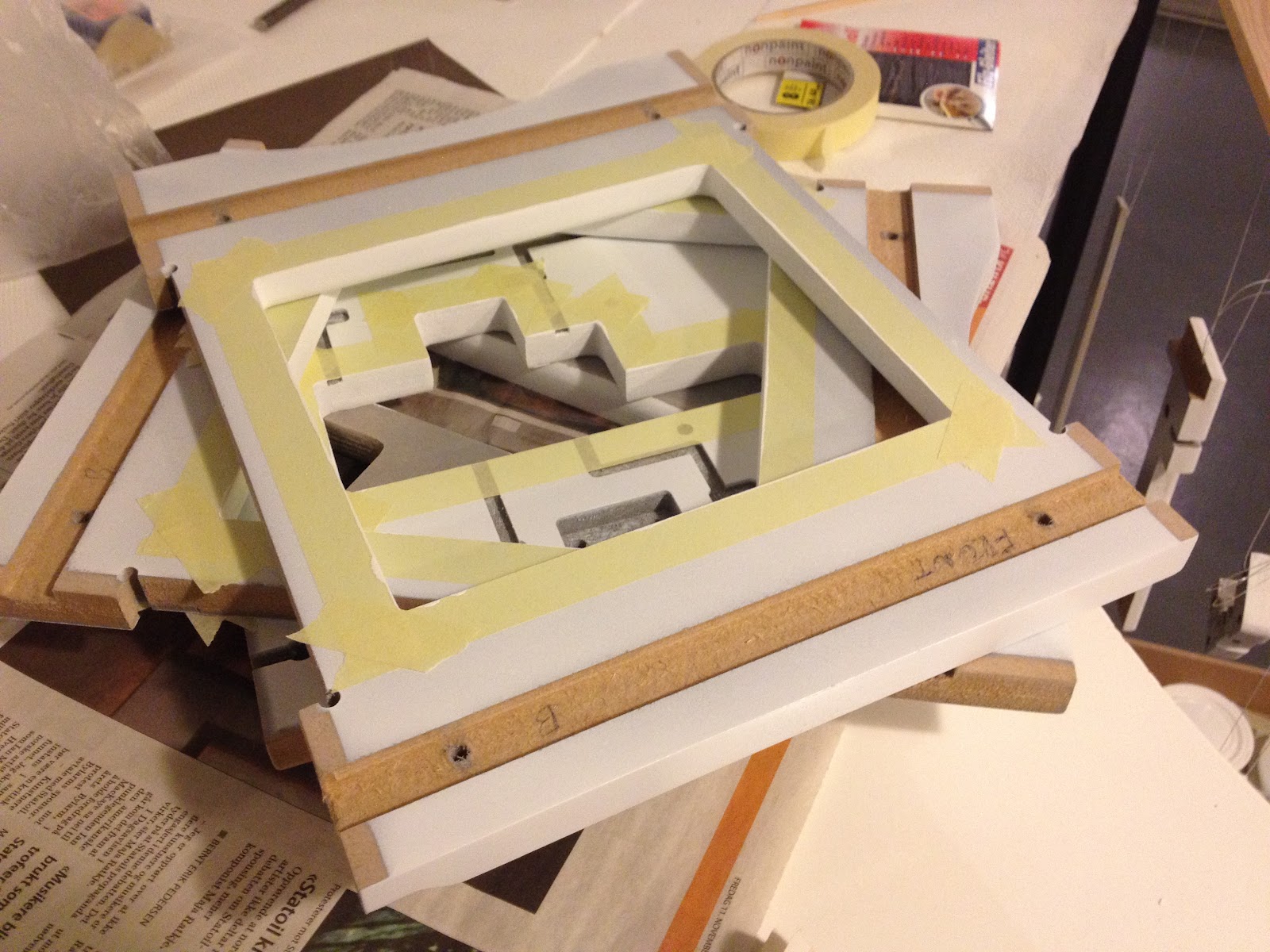
In my last post I though I were finished painting, but the perfectionist in me didn't like the finish on the sides of the parts. So, more paint!

Primed and ready...
Some of the other parts.
Masked and ready for paint.
Since my significant other loves purple my reasoning was that maybe if I used that as the secondary color she might be persuaded to let me keep the printer in the living room :)

Purple it is!
After painting...
Finally being happy with the paint job it was time to move on with the assembly. The biggest issue was the error in the routing of the feeder part. At first I thought I would see if I could fix it myself since I only needed to drill some holes and remove some MDF to make room for the parts. Well, a seemingly easy job botched up mainly because of me sitting on my living room floor and not having access to a proper workbench.
Result of drilling in MDF without proper support.
After e-mailing Richard about this he promptly replied that he was not only going to send me new feeder parts, but also the newest revision of the hot-end as compensation. That's what I call great customer support - thanks Richard! :) A couple of weeks later I was ready to proceed.

The new hot-end with a single extruder. There are room for
two extruders if I on a later point want to add one more. 
Seen from the top.
The main difference between the old and the new extruder being a connection piece made of peek (the brown plastic in the picture). Peek handles heat very well so we'll have no issues with the plastic in the bowden tube retainer (blue) melting and we can skip the fan and heat sink as well simplifying the design greatly.

EDIT: As mentioned in the comments below the way the print-head is assembled in the pictures is wrong! The correct way is (from the top): push fitting, MDF (upside down from what's seen here), peek and then the nozzle. Unfortunately I forgot to take new pictures before installing the print head in the SUMPOD.

Belt in place for the X-axis.
The Y-axis in place. I took some extra time prettying up the
cables and at the same time making everything more tidy.
In progress with the final connections underneath the
SUMPOD.
Crimping the connectors took a while since I wanted to do
it properly and didn't have the proper tool. Crimp, solder
and then add the plastic casing.
I imagine final assembly took about 3-4 days in total. Much of that time was checking and double-checking the instructions with the SUMPOD forum as well as the other build-logs out there. Instructions were not always straight forward or the same and I wanted to avoid having to pull anything apart - better to get it right in the first place!

Although I did test the electronics before I assembled the SUMPOD it was a bit nerve wrecking the first time I turned on the unit. To my astonishment everything worked perfectly! From what I had read on the forum I knew some people had issues with the feed mechanism not working in ReplicatorG so I weren't surprised my unit had the same issue. A quick swap to Pronterface showed the feeder worked fine albeit reversely. Changing the Configuration.h file in the Sprinter firmware fixed that issue.
// Inverting axis direction
const bool INVERT_X_DIR = true;
const bool INVERT_Y_DIR = true;
const bool INVERT_Z_DIR = true;
const bool INVERT_E_DIR = false;
The malfunctioning feeder in ReplicatorG is caused by a bug which is fixed, but hasn't made it into the main code yet. If you are on windows you can use ReplicatorG 0034 for 5D, or supposedly 0029 should work as well. It doesn't yet for me...

Next up were calibration. Unfortunately I didn't have much to go with on how to to that exactly so to make a long story short I ended up with a nasty collision between the printer head and the print bed - even though I had my finger on the power button. The result of the collision left my printer bed crooked on the Y-axis. I don't have a picture to show this, but it is visible to the eye and I guess it's about 3mm difference between the top and bottom. It was all my fault and being angry with myself I had to leave the project alone a couple of days before I could continue. Not necessarily a bad thing since it gives the subconscious time to work out whatever needs to be done to fix the problem. Which in this case were; where is Z = 0.

Browsing the forums and the Wiki led me to this g-code from Airtripper. Experimenting with the Z value (and my finger on the off-button) I started with the high value of 10.0 and working my way down.
My setting of Z = 2.5
With Z = 2.5 I get the correct distance from the printer head to the bed. It's not ideal yet since the bed is not flat compared to the print head on the Y-axis. Anyways; I'll look into the Sprinter firmware to see if I can set the value there or if I have to pre-process all my g-code with this value.

Pronterface
Since I still have issues with ReplicatorG I continued to use Pronterface. Although it doesn't have a 3D view of the model to be printed, like ReplicatorG has, I love the manual controls. The temperature monitoring also works as expected. That's another area where I have had issues with ReplicatorG with it only sporadically showing any readings. I'm not sure if that has anything to do with me running 0029 or the Sprinter firmware, but I would guess the former since Pronterface works fine.

First print! Red and pretty :D
Closeup of the first print. Seems like the registration is good!
The lens is to blame for the apparent skewing.
I'm impressed by the quality of the print and what little can be seen of artifacts I believe can be linked to the bed and the distance between the bed and printer head being a bit too high. I can clearly see the thread, but playing with the parameters of Skeinforge should allow for higher resolution in that aspect.

I did try to remove the raft, but it's firmly stuck so a knife is needed. After I have made some adjustments I'll try to print without a raft and see how that goes.

What remains now is to get the bed leveled. I'm considering a variation of the mechanism described on the SUMPOD wiki, but it's hard to source springs here in Norway so if my RC-Car spring spare-part idea doesn't pan out I have to think about something else.

I also need to work on the display contrast. Not that I use it, but It's nice to have it working anyway. With the current setup I use a 3K resistor which is a bit much since the contrast is too low.

I have purchased Alibre Design for the purpose of 3D modeling of parts, but since my main computer at home is a Mac I'll keep an eye on the new Autodesk Inventor Fusion as well. It's a bit of a hassle to boot into bootcamp every time I need to fix a part. Now on to the next project - where self-printed plastic parts most likely will play a great part :) After all; I have around 7 Kg of PLA and ABS plastics to play with...