Showing posts with label 3D. Show all posts

Saturday, June 6, 2015

Explosive plates for VFX

Disclaimer: this is a big "do not try this at home"-post as it involves flammable gasses and explosions, so don't! Wait, who am I kidding - you're totally going to try this at home aren't you... just don't say I didn't warn you when you stand there missing an eyebrow!

Light it up! Watch your fingers!
So, we recently did a project at work where we needed some fiery effects to spice up a car shot. To be precise we wanted the car, a CG rendered Lamborghini Aventador, to have exhaust flames - and really cool ones at that.

The usual route would be to create these digitally using a variety of tools, for example Trapcode Particular. As we had just a week and a half to produce the whole spot we had to be creative to make sure we finished on time. That meant going old school and shooting a practical effect in camera - allowing us to bag that particular effect in 20 minutes and focus on the rest of the 3D and compositing instead.


What you need
1 x small plastic bottle. We used a 33cl bottle from Ramlösa. You can go bigger, but this was plenty to get the effect we were looking for.
1 x refill canister of Butane gas (ie lighter fluid). You probably can use a regular lighter as well, but you'll need more time to fill the bottle.
1 x lighter, preferably the "long nose" or "expanded reach" kind. If you have long matches that'll work as well. The important part is to keep your fingers safe.
1 x roll of gaffer tape to anchor the bottle to something sturdy so it doesn't shoot off when ignited.
1 x needle, nail or piece of steel wire. I used a paper clip.
1 x pliers to hold the poking device (see previous)
1 x camera on tripod
1 x dark room
Enough safety glasses for everyone present

Construction
There's not much too it really. Holding the nail in the pliers heat it using the lighter. Then, quickly, poke a hole in the bottom part of the bottle. You might have to reheat the nail a couple of times to be able to expand the hole so it becomes big enough.

Just about perfect

Execution
First of all make sure you are in a well ventilated room where there's nothing flammable.

You'll need something sturdy and heavy enough to fasten the bottle to. This way it won't fly away when you ignite the gas. Gaffer tape is nice to use for the fastening. If you get the matte black kind it can also be used to make sure the bottle doesn't reflect any of the light - making the compositing easier later on.

Set up your camera and frame your shot. Now we add the gas.

Add a tiny amount of liquid gas (less than a second)
Insert the butane gas nozzle into the hole you made earlier and give it a quick push. You don't need much since it will be liquid when pushing the container down onto the bottle. To much butane will not create a bigger explosion since the air/gas mix will be wrong resulting in no explosion at all. Put the butane canister somewhere safe away from everything.

Now turn on the camera, turn off the light in the room and set the flame from the lighter to the small where you added the gas. If you got the mix correct you will hear a satisfying pop and see a bluish flame. If not you might try to add some oxygen. A bicycle pump should work. Use the small hole for this as well. Keep going until all the gas has been burned away.


Before trying again you have to add fresh oxygen by using the pump for a little while more. Add more gas, light, retry.

Ooh, pretty!
Only steps left is to choose best part of shot and add to comp. I'm not going to go into that part here since it's fairly trivial.

And the final TVC


Saturday, August 9, 2014

PRINTinZ printer plate

On another note; I'm extremely pleased with the printer plate from PRINTinZ. I'm using the 140x140 mm printer plate which fits my printable area quite nicely.

The prints stick extremely well to the surface even when printing cold (PLA). Although too little clearance between the hotend and the surface might have it stick too well on thinner prints so be careful.

Failed print, not because of the printer plate though.

It is great to be able to lift out the whole printer plate instead of having to fiddle inside the printer when removing the print. Detaching the print from the plate is surprisingly easy. Instead of having to use a sharp knife you just twist and bend the plate and the print pops right off - as long as it's not too flexible.

The above part is 120mm in diameter and that's the biggest footprint I've managed to print to date. Previously the parts would always pop off before the print was done - even with a heated print-bed and using kapton or blue tape.

A funny thing is that when I removed the plate and placed it on the table, before removing the part, it was quite warped by the print. The finished part is a bit warped, but in this case it won't matter, but it's something I'll have to look into in the future.

Having dialed in the new E3D v6 hotend the new setup is starting to look quite nice - best quality prints so far :)

The quantum mechanics of 3D printers

Sometimes it would one could believe 3D printer have quantum properties. You have to actively observe it to get the expected result. Whenever you look away something goes wrong...

Monday, March 17, 2014

Another Rebuild

It seems most of the posts on this blog has been about me rebuilding my 3D printer. Well, hopefully this will be the last one in a while as I have several other projects that are in need of parts and I'd rather spend time on them than on another teardown/rebuild.

I were quite happy with the performance on my previous extruder mechanism, although it was supposed to be temporary. Combined with the J-Head I got very nice prints for a while.


When the extruder broke down I tried a couple of e-bay replacements but did not quite get the performance (or fit with my printer) I was looking for. At the same time the J-Head started acting up (leakage and stuff) so I needed to find a replacement for that as well.

After a bit of research I ended up buying a Bulldog Lite Extruder from their Indiegogo campaign and was pleasantly surprised that they shipped them right away with no waiting at all. Although a bit heavy it's beautifully machined and well put together. The "Lite" comes without the gearbox which makes it a bit lighter, but is only suitable for 1.75mm filament. Secondly I ordered the E3D v5 hotend which has gotten great reviews. Going with an all-metal-hotend made sense this time around since there's no peek or PTFE that can melt/be deformed.

One thing about about the Bulldog / E3D combo that isn't perfect is the mating between the two. They are both fabricated to follow the J-Head "standard" so you can just slide the stem into the extruder, but there's quite a bit of slack along the z-axis so I made some shims out of regular plastic. 4 of these did the trick.


It took me a while to get everything put together, as I also switched the printer firmware from my stock Sprinter firmware, delivered with the SUMPOD, over to the latest Marlin.

Now I finally have a working printer again. And I must say, I'm very pleased with the quality of the prints as well as the new functionality in Marlin. The printer even sounds better!


My first print were a camera stand for one of my Raspberry Pi's. This print was sliced with .3 mm layer height so it's a bit rough, but I opted for speed before beauty this time. I've made the design available on Thingiverse as well.

Until next time!

Thursday, May 9, 2013

New Spool Holder

I had some 8 mm carbon rods laying around and figured my 3D printer needed an upgrade for the spool holder. The rods are nice and long (50 cm each) and I originally intended them for a quad copter build, but I found rc-helicopter tail-rotors made of aluminum to be a better fit for that project.

Finished contraption.
The whole printer/spool holder assembly is quite high, but it saves space on the table at least. It's this high by design since the y-axis moves back and forth and having a bit of distance between the print head and the spool is good in that case.

Closeup of the spool holder.
For the center rod I used a threaded rod. This makes the centering of the bearings easier and also adds to the stability by allowing us to tighten the hold around the bracket from the vertical rod a bit.

Oh, and it rolls so much better than my last try. The design can be downloaded from Thingiverse.

Tuesday, April 30, 2013

Largest print yet

I finished a 15-hour print yesterday. As it didn't finish Sunday, we had cinema tickets and I really don't want the printer to be running when I'm not in the room, I had to pause it and continue yesterday.

Designed in Autodesk Inventor
Pausing the print didn't pose a problem, except for the operator error. I wanted to increase the distance between the print head and the part, while the head cooled down, and indadvertedly pressed move z 10 mm in the wrong direction... The print head buried itself well and good into the model, but when I reversed the direction the damage wasn't too bad. After a bit of cleanup the next day I could continue the print. Kinda lucky there.


The print came out pretty good, except for two layers around the point where I paused and that's totally my fault. By being more careful I'm sure pausing a print will cause no artifacts in the future.

This print took quite a while and I'm pretty sure I can increase the print speed since it clocks in at about 14 mm/sec at the moment. If only there was an option in Slic3r where it would speed up on longer stretches and then slow down around bends or where it goes back and forth rapidly. One for the wish list.

Oh, and what is it you might ask? Its a new stepper motor holder for the y-axis on my Sumpod.

Sunday, June 3, 2012

Inventor Fusion

Since I tend to stay in OS X on my iMac the only real reason i boot into bootcamp and Windows 7 is when I need to do something in Alibre Design. Unfortunately Alibre is Windows only and from what I gather (please correct me if I'm wrong) they have no plans to port it to other platforms. Not that I blame them - it's generally a huge task to convert a program from Direct-X to OpenGL. Especially when you have tons of legacy code.

So today I got my fill of jumping back and forth between OS'es so I thought it was time to check out Inventor Fusion for Mac by Autodesk. Luckily they have a free technology preview of this software which I installed it a while ago - just never got around to test.

First impression of the user interface was good, although a bit more simplistic than Alibre, followed by the obligatory; "how do I do this and that in this software". After a couple of quick-run-through videos on YouTube courtesy of Autodesk I had a rudimentary understanding of the software.

Upper part of outrunner motor bracket designed in Inventor Fusion.
Although some operations are a bit tricky I think it's more about figuring out "the correct procedure" to get stuff done so by playing around with it a bit more I think the overall experience is going to get better.

Since this still is a technology preview it crashed on several occasions, which is to be expected I guess, even though the operations I did were on simple objects. It even corrupting my scene file, but yet again my (paranoid?) habit of saving new versions paid off so no big loss.

Over all it is much faster to fire up Inventor than booting to Windows so I think I'll stick with it, at least for simple objects, for now.

Monday, May 28, 2012

The Saga of The 3D Printer

It's been a long journey, but now, nearly 10 months after I first ordered my 3D printer it's finally done! Well, as done as a gizmo like this is ever going to be I guess - it will forever be a work in progress with parts being tuned and such.

In my last post I though I were finished painting, but the perfectionist in me didn't like the finish on the sides of the parts. So, more paint!

Primed and ready...
Some of the other parts.
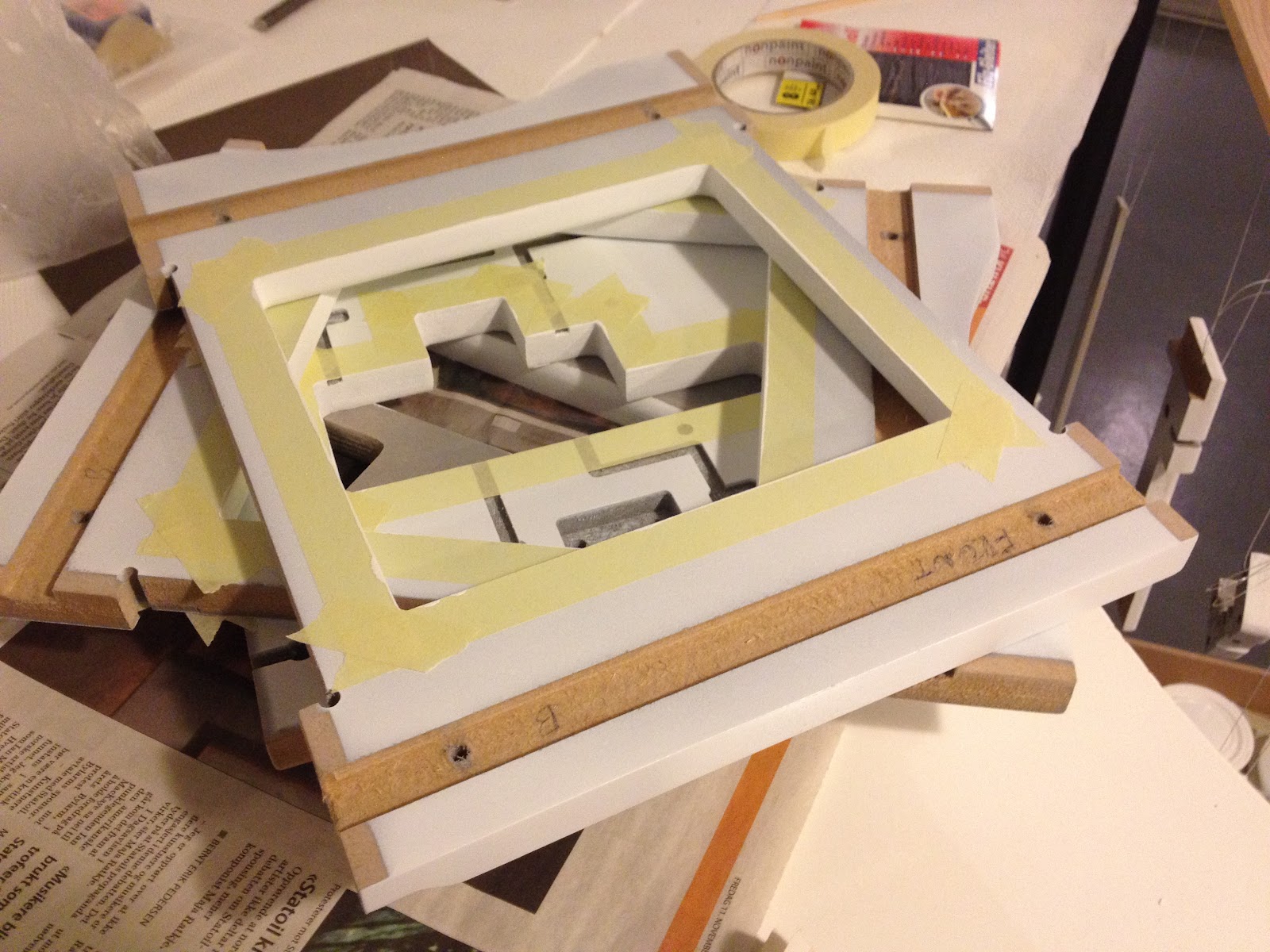
Masked and ready for paint.
Since my significant other loves purple my reasoning was that maybe if I used that as the secondary color she might be persuaded to let me keep the printer in the living room :)

Purple it is!
After painting...
Finally being happy with the paint job it was time to move on with the assembly. The biggest issue was the error in the routing of the feeder part. At first I thought I would see if I could fix it myself since I only needed to drill some holes and remove some MDF to make room for the parts. Well, a seemingly easy job botched up mainly because of me sitting on my living room floor and not having access to a proper workbench.
Result of drilling in MDF without proper support.
After e-mailing Richard about this he promptly replied that he was not only going to send me new feeder parts, but also the newest revision of the hot-end as compensation. That's what I call great customer support - thanks Richard! :) A couple of weeks later I was ready to proceed.

The new hot-end with a single extruder. There are room for
two extruders if I on a later point want to add one more. 
Seen from the top.
The main difference between the old and the new extruder being a connection piece made of peek (the brown plastic in the picture). Peek handles heat very well so we'll have no issues with the plastic in the bowden tube retainer (blue) melting and we can skip the fan and heat sink as well simplifying the design greatly.

EDIT: As mentioned in the comments below the way the print-head is assembled in the pictures is wrong! The correct way is (from the top): push fitting, MDF (upside down from what's seen here), peek and then the nozzle. Unfortunately I forgot to take new pictures before installing the print head in the SUMPOD.

Belt in place for the X-axis.
The Y-axis in place. I took some extra time prettying up the
cables and at the same time making everything more tidy.
In progress with the final connections underneath the
SUMPOD.
Crimping the connectors took a while since I wanted to do
it properly and didn't have the proper tool. Crimp, solder
and then add the plastic casing.
I imagine final assembly took about 3-4 days in total. Much of that time was checking and double-checking the instructions with the SUMPOD forum as well as the other build-logs out there. Instructions were not always straight forward or the same and I wanted to avoid having to pull anything apart - better to get it right in the first place!

Although I did test the electronics before I assembled the SUMPOD it was a bit nerve wrecking the first time I turned on the unit. To my astonishment everything worked perfectly! From what I had read on the forum I knew some people had issues with the feed mechanism not working in ReplicatorG so I weren't surprised my unit had the same issue. A quick swap to Pronterface showed the feeder worked fine albeit reversely. Changing the Configuration.h file in the Sprinter firmware fixed that issue.
// Inverting axis direction
const bool INVERT_X_DIR = true;
const bool INVERT_Y_DIR = true;
const bool INVERT_Z_DIR = true;
const bool INVERT_E_DIR = false;
The malfunctioning feeder in ReplicatorG is caused by a bug which is fixed, but hasn't made it into the main code yet. If you are on windows you can use ReplicatorG 0034 for 5D, or supposedly 0029 should work as well. It doesn't yet for me...

Next up were calibration. Unfortunately I didn't have much to go with on how to to that exactly so to make a long story short I ended up with a nasty collision between the printer head and the print bed - even though I had my finger on the power button. The result of the collision left my printer bed crooked on the Y-axis. I don't have a picture to show this, but it is visible to the eye and I guess it's about 3mm difference between the top and bottom. It was all my fault and being angry with myself I had to leave the project alone a couple of days before I could continue. Not necessarily a bad thing since it gives the subconscious time to work out whatever needs to be done to fix the problem. Which in this case were; where is Z = 0.

Browsing the forums and the Wiki led me to this g-code from Airtripper. Experimenting with the Z value (and my finger on the off-button) I started with the high value of 10.0 and working my way down.
My setting of Z = 2.5
With Z = 2.5 I get the correct distance from the printer head to the bed. It's not ideal yet since the bed is not flat compared to the print head on the Y-axis. Anyways; I'll look into the Sprinter firmware to see if I can set the value there or if I have to pre-process all my g-code with this value.

Pronterface
Since I still have issues with ReplicatorG I continued to use Pronterface. Although it doesn't have a 3D view of the model to be printed, like ReplicatorG has, I love the manual controls. The temperature monitoring also works as expected. That's another area where I have had issues with ReplicatorG with it only sporadically showing any readings. I'm not sure if that has anything to do with me running 0029 or the Sprinter firmware, but I would guess the former since Pronterface works fine.

First print! Red and pretty :D
Closeup of the first print. Seems like the registration is good!
The lens is to blame for the apparent skewing.
I'm impressed by the quality of the print and what little can be seen of artifacts I believe can be linked to the bed and the distance between the bed and printer head being a bit too high. I can clearly see the thread, but playing with the parameters of Skeinforge should allow for higher resolution in that aspect.

I did try to remove the raft, but it's firmly stuck so a knife is needed. After I have made some adjustments I'll try to print without a raft and see how that goes.

What remains now is to get the bed leveled. I'm considering a variation of the mechanism described on the SUMPOD wiki, but it's hard to source springs here in Norway so if my RC-Car spring spare-part idea doesn't pan out I have to think about something else.

I also need to work on the display contrast. Not that I use it, but It's nice to have it working anyway. With the current setup I use a 3K resistor which is a bit much since the contrast is too low.

I have purchased Alibre Design for the purpose of 3D modeling of parts, but since my main computer at home is a Mac I'll keep an eye on the new Autodesk Inventor Fusion as well. It's a bit of a hassle to boot into bootcamp every time I need to fix a part. Now on to the next project - where self-printed plastic parts most likely will play a great part :) After all; I have around 7 Kg of PLA and ABS plastics to play with...

Thursday, April 26, 2012

Back To The Roots

After watching "Iron Sky" and reading about the production at CGSociety I got the urge to check out Lightwave again. This is after all the software that got me started with 3D all those years ago. After a brief stint with 3D Studio 4 run under MS-DOS I tried my hands on Lightwave 4 - instant love! I kept using Lightwave for a couple of years, but left it shortly after v6 came out seeing Maya as the future. I believe Maya was at v2.5 back then. Although I kept using Lightwave on and off for a couple of years Maya eventually replaced it completely.

What I remember I liked about Lightwave was the SubD's and the integrated renderer - which was very good. The modelling tools suited me quite well as well, but after learning the Maya tools I really didn't look back.

Head model courtesy Dance Macabre @ TurboSquid

Lightwave 11, as of today, has a free 30 day trial. Registering gets you a serial that unlocks all functionality and removes water mark - which is nice.

The layout is pretty much the same as I remember from Lightwave 6. You still have two different programs, modeller and layout. I must admit I'm a bit rusty not having touched the program in 10-12 years, but I managed to assign some shaders, add fur, light and render a small test.

Although 999 free render licenses are tempting I don't think I'll be jumping back.